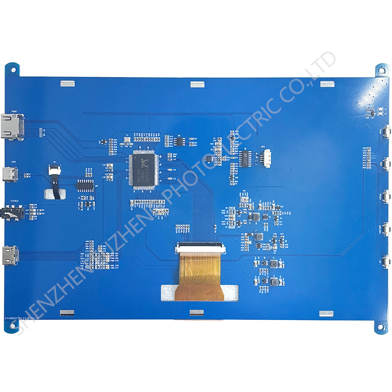
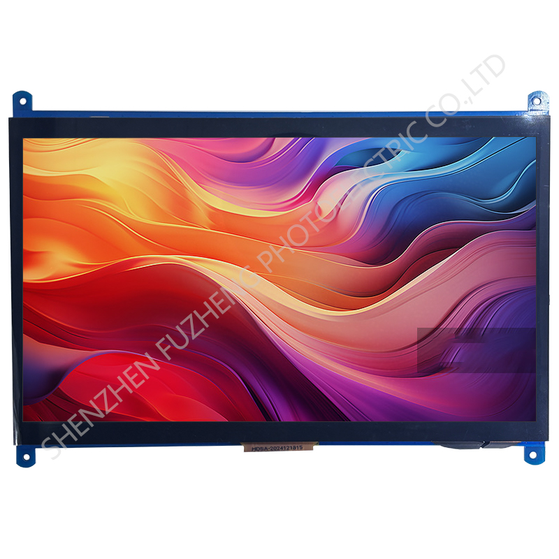
10.1 inch TFT RGB display 1024*600 with touch screen
FZ1001R50-TP is a color active matrix LCD module incorporating amorphous silicon TFT (Thin Film Transistor). It is composed of a color TFT-LCD panel, driver IC, FPC and a back light unit. The module display area contains 1024x 600pixels. This product accords with RoHS environmental criterion.
| Item | Contents | Unit |
| Model | FZ10L140-TP | |
| LCD Type | TFT | / |
| Viewing direction | ALL | O' Clock |
| Size | 10.1 inch | inch |
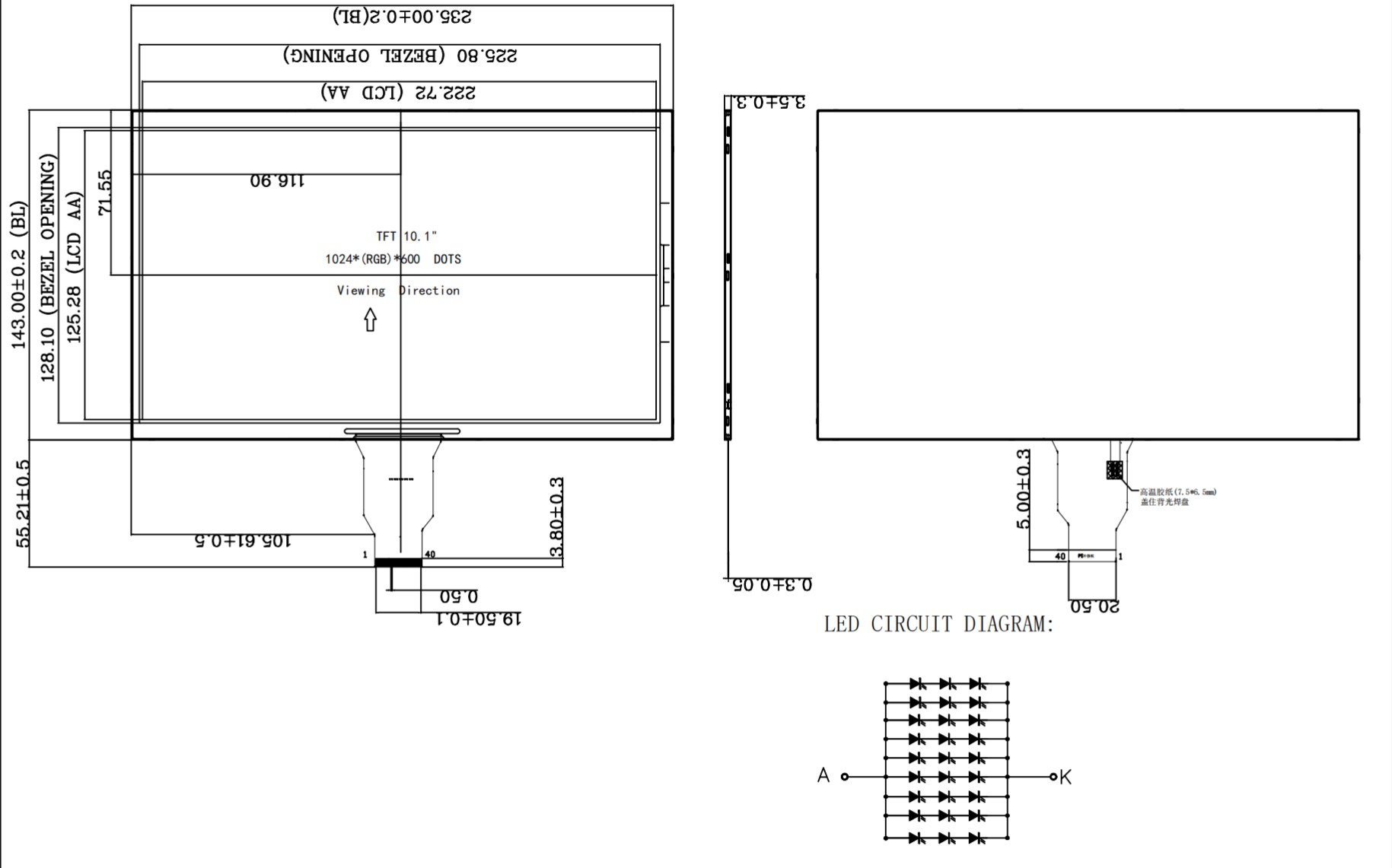
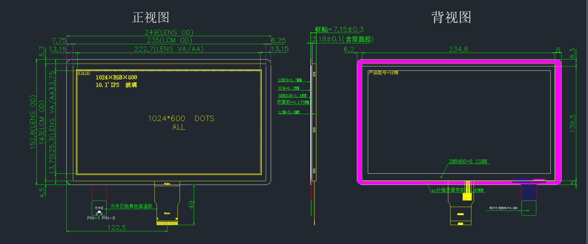
| Module outline (W x HxD) | 235x143x3.5 | mm |
| Active area (WxH) | 222.72x125.28 | mm |
| Resolution (pixels) | 1024(RGB) x600 | / |
| Interface Type | Parallel RGB 24-bit | / |
| Input voltage | 3.3 | V |
| Luminance | 400 | cd/m2 |
| Backlight type and color | 6*7chips white LED | |
| Controller IC | ||
| Touch type | CTP (capacitive touch panel) | |
| LED Life span: | 30000 | hour |
| Operating temperature range: | -20 -- 70 °C | |
| Storage temperature range: | -30 -- 80 °C |
ELECTRICAL CHARACTERISTICS
Item | Symbol | Values | Unit | Remark | ||
Min. | Typ. | Max. | ||||
Power Voltage | DVDD | 3.0 | 3.3 | 3.6 | V | |
AVDD | 10.65 | 10.85 | 11.05 | V | ||
VGH | 20 | 21 | 22 | V | ||
VGL | - | -8 | - | V | ||
Input signal voltage | VCOM | 3.6 | 3.8 | 4.2 | V | |
Input logic high voltage | VIH | 0.9VDD | - | DVDD | V | |
Input logic low voltage | VIL | 0 | - | 0.1DVDD | V | |
Note1:If users use the product out off the environmemtal operation range(temperature and humidity),it will have visual quality concerns.
Note2:Be sure to apply DVDD and VGL to the LCD first,and then apply VGH
Note3:DVDD setting should match the signals output voltage(refer to Note4)of customer's system board.
Note4:DCLK,HS,VS,RESET,U/D,L/R,DE,R0-R7.G0-G7,B0-B7,MODE,DITHB.
Note5:Typical VCOM is only a reference value,it must be optimized according to each LCM. Please ues VR and base on below application circuit.
Current Consumption
Item | Symbol | Values | Unit | Remark | ||
Min. | Typ. | Max. | ||||
Current for Driver
| IGH | - | 0.50 | 1 | mA | VGH=18.0V |
IGL | - | 0.50 | 1 | mA | VGL=-6.0V | |
IVDD | - | 8 | 15 | mA | VDD=3.3V | |
IAVDD | - | 30 | 40 | mA | AVDD=9.6V | |
BACKLIGHT CHARACTERISTICS
Item | Symbol | Min | Typ | Max | Unit | Condition |
Forward voltage | Vf | - | 9.0 | - | V | If=140mA |
Luminance | Lv | - | 400 | - | cd/m2 | If=140mA |
Number of LED | -- | 42 | Piece | -- | ||
Connection mode | P | 6chips serial *7 | -- | -- | ||
INTERFACE PIN CONNECTIONS
Pin.No | Symbol | Function |
1,2 | NC | NC |
3,4 | NC | NC |
5 | GND | Power ground |
6 | VCOM | Common Voltage |
7 | DVDD | Digital Power |
8 | MODE | DE/SYNC mode select. Normally pull high H: DE mode. L: HSD/VSD mode |
9: | DE | Data Enable signal. |
10 | VSD | Vertical sync input. Negative polarity |
11 | HSD | Horizontal sync input. Negative polarity |
12-19 | B7-R0 | Blue Data |
20-27 | G7-G0 | Green Data |
28-35 | R7-R0 | Red Data |
36 | GND | Ground |
37 | DCLK | Colock signal |
38 | GND | Ground |
39 | SHLR | Left or Right Display Control |
40 | UPDN | Up / Down Display Control |
41 | VDDG | Positive Power for TFT |
42 | VEEG | Negative Power for TFT |
43 | AVDD | Analog Power |
44 | RSTB | Global reset pin. Active low to enter reset state. Suggest to connecting with an RC reset circuit for stability. Normally pull high. (R=10KΩ,C=1μF) |
45 | NC | Not connect |
46 | VCOM | Common Voltage |
47 | DITH | Dithering setting DITH=”H” 6bit resolution(last 2 bit of input data truncated) DITH=”L” 8bit resolution(default setting) |
48 | GND | Power ground |
49 | NC | Not connect |
50 | NC | Not connect |
TP-PIN
1 | RST | Touch Reset Signal |
2 | VDD | Touch Power supply |
3 | GND | Ground |
4 | INT | Touch Interrupt |
5 | SDA | ouch IIC Data signal |
6 | SCA | Touch IIC Clock signal |